

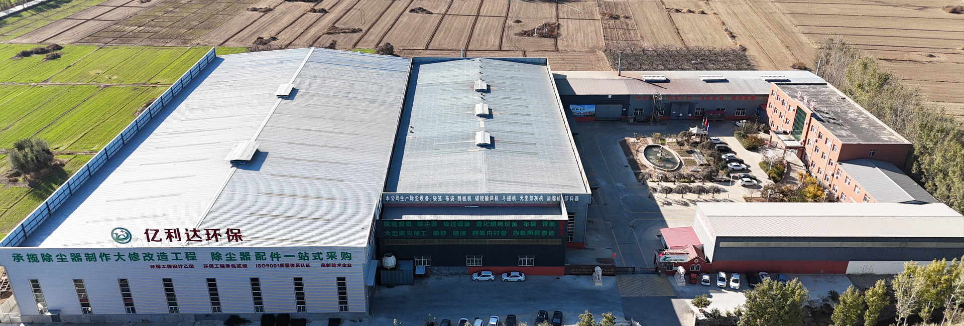

- Botou Yilida Environmental Protection Machinery and Equipment Co., Ltd
- Contact:Ms. Zhang
- Email: yilida@yilida-dustcollectors.com
- Add: Xiaoyuan Village, Qiqiao Town, Botou City, Cangzhou City, Hebei Province
Author:yilida Time:2026-08-31 17:59:58 Number of views:108Second-rate
A grain handling operator told me his "new" dust collector was pulling only 60% of its rated airflow, and the supplier insisted the collector was fine. It was. The problem was the rotary airlock at the hopper bottom: the rotor tips had worn, the clearances had opened up, and the valve was leaking more air backward through the system than it was discharging dust forward. The collector was fighting a vacuum leak it could never win. Replacing the airlock with a properly specified, tight-clearance unit restored full airflow overnight.
The rotary airlock valve — sometimes called a rotary feeder, rotary valve, or airlock — is among the smallest, cheapest, and most misunderstood components in an industrial dust collection system. It sits at the bottom of the hopper and performs a deceptively simple job: let dust out while keeping air from flowing back in. When it does that job well, nobody notices. When it fails, the entire dust collection system underperforms, and operators blame everything except the valve.
An industrial dust collector operates under negative pressure (the fan pulls air through the filter). The hopper beneath the filter accumulates the dust that the rappers or pulse cleaning dislodge. At the bottom of that hopper is the airlock. Its rotor — a rotating star or pocket wheel — carries discrete pockets of dust from the top (under vacuum) to the bottom (at atmospheric pressure), discharging it into a conveyor, drum, or bin.
The critical function is sealing. Air wants to rush from the high-pressure outside environment, up through the valve, and into the negative-pressure hopper. If the valve leaks, that air short-circuits the filtration system, reduces effective capture at the hoods, wastes fan energy, and can even fluidize the dust in the hopper, preventing it from discharging. A good airlock passes dust but not air.
The standard configuration. Dust drops in from the top, the rotor pockets carry it around, and it drops out the bottom by gravity into the discharge chute. The inlet and outlet are vertically aligned. This is the right choice for free-flowing dust discharging into a bin, screw conveyor, or pneumatic line below.
In a blow-through valve, a small air purge enters near the top of the rotor and pushes the dust out the bottom discharge, helping evacuate sticky or poor-flowing material and preventing buildup on the rotor. The outlet connects to a pneumatic conveying line or a pressured zone. Blow-through designs use more air but handle difficult materials better. They are specified when the dust tends to hang up in a standard drop-through valve.
The rotor is the heart of the valve, and its design determines both sealing and material handling behavior.
The most common design: pockets open at both ends of the rotor, mounted on a through shaft. Simple, easy to clean, and adequate for most free-flowing dusts. The end clearance between the rotor and the end plate is the primary sealing surface.
The pockets are closed at the ends by discs, eliminating the end-plate clearance leak path. This roughly doubles the sealing effectiveness at the rotor ends and is specified for fine, aeratable dusts (cement, fly ash, flour) where even small leaks cause significant air bypass and fluidization.
For food, pharmaceutical, and color-change applications, the rotor can be removed or accessed without tools for cleaning between batches. Sanitary designs use polished stainless steel, minimal dead spaces, and tool-free disassembly. The cost is higher, but the cleanability is essential in regulated industries.
Rotor pocket count typically ranges from 6 to 12 vanes. More vanes mean smaller pockets and better sealing (more frequent feed, less open area at any moment) but lower volumetric throughput per revolution. Fewer vanes mean larger pockets and higher capacity but more leakage per revolution. The choice balances capacity against sealing for the specific application.
The valve must discharge at least the mass of dust the collector drops into the hopper, with margin. Capacity is:
Q = N × V_pocket × ρ_bulk × RPM × η_fill
Where N is the number of pockets, V_pocket is the pocket volume, ρ_bulk is the bulk density of the dust, RPM is rotor speed, and η_fill is the fill efficiency (typically 0.7–0.85 for free-flowing material, lower for poor-flowing dust). Size the valve so that at a conservative RPM (often 20–40 RPM) it handles the peak dust loading with margin; oversizing marginally is safer than running at the edge of capacity, which causes rotor stall and motor overload.
The valve must withstand the pressure differential across it — typically the hopper vacuum (a few hundred to a few thousand Pascals) plus any purge or conveying pressure. Standard valves are rated for modest differentials; high-differential applications (pneumatic conveying lines at 0.5–1 bar) require heavy-duty rotors, reinforced housings, and precision clearances. Specify the differential explicitly — a valve rated for free gravity discharge will leak or bind under conveying pressure.
Hot dust (above 150°C) requires heat-resistant seals, possibly water-cooled rotors or high-temperature packings, and materials that retain strength at temperature. Carbon steel suffices for ambient, non-corrosive dust; stainless steel is specified for food, pharmaceutical, or corrosive applications. The rotor-to-housing clearance must account for thermal expansion — a valve that fits tightly cold may bind when hot.
Three sealing interfaces matter:
Tip clearance: The gap between the rotor vane tips and the housing bore. Factory-new clearance is typically 0.05–0.15 mm. As the rotor wears (abrading against the housing or carried grit), this opens, and leakage climbs. Precision-machined housings and abrasion-resistant rotors extend the tight-clearance life.
End clearance: The gap between the rotor ends and the end plates. Closed-end rotors eliminate this path. For open-end rotors, end clearance is a primary leak route and should be minimized.
Inlet/outlet sealing: The transition between the hopper flange and the valve body, and between the valve and the discharge chute, must be gasketed and bolted to prevent flange leaks that bypass the entire rotor.
Hard, sharp dust (silica, alumina, mineral fines) wears rotor tips and housing bores. Symptoms: rising air leakage, falling discharge efficiency, increasing power draw. Mitigation: abrasion-resistant rotors (hard-faced or ceramic-tipped vanes), harder housing liners, and proactive clearance inspection.
Caused by oversized dust feed, material bridging in the pockets, or a jammed foreign object. The motor trips on overload or the coupling shears. Mitigation: size with margin, add a jam-release coupling or shear pin, and ensure upstream material flow is controlled.
Sticky, moist, or cohesive dust accumulates on rotor surfaces and in pockets, reducing capacity and eventually stalling the rotor. Mitigation: blow-through design, heated valve for moisture-prone dust, polished internal surfaces, and in severe cases, a rotor with scrapers.
Packing glands and shaft seals wear, leaking dust and air at the shaft. For dust-tight applications, specify outboard bearings (bearing outside the dust zone) and quality shaft seals. Ingress of dust into the bearing is the most common cause of bearing failure in airlocks.
Listen: A healthy airlock has a steady rhythmic pulse. Grinding, scraping, or irregular loading indicates wear or binding.
Inspect clearances: During scheduled maintenance, measure rotor tip and end clearance. When they exceed the manufacturer's limit, rebuild or replace the rotor.
Check the drive: Chain, gearmotor, or direct-drive — verify alignment, lubrication, and that the RPM matches the design. A slowing rotor discharges less dust.
Verify discharge: Confirm material is actually leaving the valve. A valve spinning freely but not discharging means internal buildup or a blocked outlet chute.
Lubricate bearings: Outboard bearings need periodic grease; follow the manufacturer's schedule, and protect them from dust ingress.
The airlock is not an isolated component. Its performance depends on the hopper above it and the discharge system below it:
Hopper design: The hopper must deliver dust uniformly to the valve inlet without bridging. Steep walls (60°+), adequate outlet size, and a hopper shape that feeds the full rotor width prevent starvation and uneven wear.
Discharge matching: The device below — screw conveyor, rotary valve to bin, pneumatic line — must accept the valve's discharge rate. A bottleneck below causes reflux and hopper level rise.
Level control: A high-level probe in the hopper protects against the valve failing and dust rising into the filter zone. Interlock the collector or alert on high level.
The rotary airlock valve is small, inexpensive, and absolutely essential. A dust collection system is only as tight as its airlock — leakage at the hopper bottom undermines every dollar spent on the filter, the fan, and the ductwork. Specifying the right rotor type, sizing for the actual dust load with margin, and maintaining the clearances protects the performance of the entire system.
For plants handling fine, aeratable, or hot dust, the modest premium for a closed-end rotor, abrasion-resistant construction, and precision clearances pays back many times over in avoided airflow loss and extended service life. Treat the airlock as a precision sealing component, not a commodity fitting, and the rest of the system will reward you.
Our factory supplies rotary airlock valves in drop-through and blow-through configurations, with open-end, closed-end, and quick-clean rotors, in carbon and stainless steel, for dust collector discharge across industrial applications. We size each valve to the actual dust characteristics, pressure differential, and temperature of your process.
American Conference of Governmental Industrial Hygienists (ACGIH). "Industrial Ventilation: A Manual of Recommended Practice for Design," 30th Edition, 2019.
National Fire Protection Association (NFPA). "Standard for the Prevention of Fire and Dust Explosions from the Manufacturing, Processing, and Handling of Combustible Particulate Solids." NFPA 654, 2023 Edition.
CEMA (Conveyor Equipment Manufacturers Association). "CEMA Standard 300: Classifications for Rotary Valves."
American Society of Mechanical Engineers (ASME). "ASME B31.3: Process Piping." Chapter on Materials and Pressure Design.
U.S. Environmental Protection Agency (EPA). "AP-42: Compilation of Air Pollutant Emission Factors," Chapter 13: Miscellaneous Sources.
National Institute for Occupational Safety and Health (NIOSH). "Dust Control Handbook for Industrial Minerals Mining and Processing." NIOSH IC 9518, 2012.
Copyright © 2025-2026 Botou Yilida Environmental Protection Machinery and Equipment Co., Ltd All Rights Reserved